What it does
Polyphase versus direct implementation of a downsampler followed by an upsampler: direct case
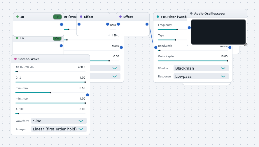
This is an elaboration of "PolyphaseVersusDirectDownsamplingEducationalExample1.dwb" whereby the signal is downsampled by a factor of 4 with an anti-aliasing filter (imported from an off-line design), then upsampled by a factor of 4 with an anti-imaging filter (imported from an off-line design created using the MATLAB code in the script-file "wwxmpl12.m" located in the wwmatlab directory). The net result is a low-pass filtering of the original signal. The point of the DrawingBoard is to demonstrate the "duality" between anti-aliasing-followed-by-downsampling, and upsampling-followd-by-anti-imaging. Play the DrawingBoard with the sinusoidal test signal (from the Combo Wave Generator) and observe the output on the oscilloscope. You will see that the ouput is a restored sinusoidal signal, almost identical to the input for signal frequencies below (approx) 5512 Hz, the low-pass filter cut-off frequency. Now gradually increase the signal frequency. As it approaches and exceeds 5512, the ouput amplitude is suppressed due to the action of the low-pass filtering.
A key point to notice in this example is that the entire re-sampling chain is implemented in the "direct" (straightforward) implementation. In other words, the anti-alias filtering is performed before the downsampling, and the up-sampling is perfomed before the anti-image filtering. This is wasteful bearing in mind that the 4-factor downsampler "throws away" 3 out of 4 samples, and the 4-factor upsampler adds 3 zero-values between successive inputs. All these values are included in the filter computations but don't contribute to the filter outputs ! There is, in fact, a considerably more efficient implementation which gives identical results. It is known as the polyphase implementation, and is demonstrated in the companion ExampleDrawingBoard "PolyphaseVersusDirectResamplingEducationalExample2.dwb" .
For a thorough discussion on polyphase filtering, see "Wavelets and Filter Banks" by Gilbert Strang and Truong Nguyen, Wellesley-Cambridge Press, 1996, and "Multirate Digital Signal Processing" by Ronald E Crochiere and Lawrence R Rabiner, Prentice Hall, 1983.
This DrawingBoard nicely illustrates the power and versatility of WaveWarp's sample-by-sample multirate audio engine.
(WaveWarp 3.0, node 1: this "FIR low-pass" loaded 139 coefficients from an off-line design file ("dec4.txt") that this version cannot reproduce tap for tap. It runs an equivalent filter instead - a 139-tap Blackman-windowed low-pass at the same 5510 Hz cutoff, matching the original's passband and its 6 dB point; an octave above the cutoff it is 111 dB down, where the 1998 filter was 66 dB down.)
(WaveWarp 3.0, node 8: this "FIR low-pass" loaded 139 coefficients from an off-line design file ("int4.txt") that this version cannot reproduce tap for tap. It runs an equivalent filter instead - a 139-tap Blackman-windowed low-pass at the same 5510 Hz cutoff, matching the original's passband and its 6 dB point; an octave above the cutoff it is 111 dB down, where the 1998 filter was 66 dB down. Its 1998 coefficients also carried the 12.04 dB interpolation gain; this block's Output gain stops at +10 dB, so this branch is 2.04 dB quieter than it was in 1998.)