← All boards
Multichannel Surround

Sine Wave Arbitrary Panner Built From Scratch_3

Plays on the mobile app
The Sine Wave Arbitrary Panner Built From Scratch_3 board in the WaveWarp DrawingBoard
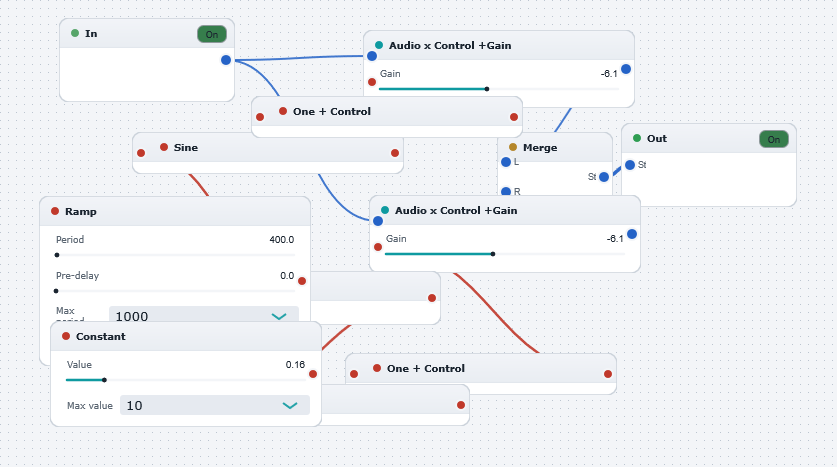
Sine Wave Arbitrary Panner Built From Scratch_3 — the board as it opens in the WaveWarp DrawingBoard.

What it does

Sinewave arbitrary panner built from scratch

A generalisation of the algorithm from the "Sinewave Panner Built From Scratch" DrawingBoard to enable an arbitrary phase separation between the left and right channels.

The auto-panner is created by multiplying a mono audio signal by separate "left" and "right" amplitude modulation signals which are then "zipped up" to form a stereo output. The Ramp Control Generator is used to generate a ramp signal which rises from 0 to 2*pi over a user-selectable duration. This ramp signal represents the (wrapped) phase of an oscillator. The Control Sine block calculates the trigonometric sine of the ramp signal which is used (via the One plus Control) block to modulate the "left" channel. The Constant Control Generator is used to generate an offset phase angle (in radians) before taking the trigonometric sine via the second "Control Sine" block and modulating the "right" channel (via the second "One plus Control" block). This implementation allows for an arbitrary user-selectable phase difference between the left and right channels. This is only one example of how to distibute the signal between the channels. Other variations on the theme are, of course, entirely possible.

Likewise, the structure can easily be extended to generate multi-channel panners instead of merely stereo (i.e. 2 channels).

Effects used

12 blocks 13 connections
In WaveWarp, 1998

How the original documented it

Sinewave arbitrary panner built from scratch A generalisation of the algorithm from the "Sinewave Panner Built From Scratch" DrawingBoard to enable an arbitrary phase separation between the left and right channels. The auto-panner is created by multiplying a mono audio signal by separate "left" and "right" amplitude modulation signals which are then "zipped up" to form a stereo output. The Ramp Control Generator is used to generate a ramp signal which rises from 0 to 2*pi over a user-selectable duration. This ramp signal represents the (wrapped) phase of an oscillator. The Control Sine block calculates the trigonometric sine of the ramp signal which is used (via the One plus Control) block to modulate the "left" channel. The Constant Control Generator is used to generate an offset phase angle (in radians) before taking the trigonometric sine via the second "Control Sine" block and modulating the "right" channel (via the second "One plus Control" block). This implementation allows for an arbitrary user-selectable phase difference between the left and right channels. This is only one example of how to distibute the signal between the channels. Other variations on the theme are, of course, entirely possible. Likewise, the structure can easily be extended to generate multi-channel panners instead of merely stereo (i.e. 2 channels).

Components used (1998)

Control SineInput WAV fileZipperOutput Stereo WAVE DriverMultiply Audio by Control with GainMultiply Audio by Control with GainOne plus ControlOne plus ControlAdd ControlsControl SineRamp Control GeneratorConstant Control Generator